
Reduction Gear
Professional Customization Services
With the continuous development of the automotive industry, there is a growing demand for customization of components. With a strong design team and advanced production equipment, the company is able to customize production according to the specific needs of customers to meet the special requirements of different models and different working conditions.
Perfect supply chain system
A mature automotive gear manufacturer often has a perfect supply chain system, which can ensure the stable supply of raw materials and efficient delivery of finished products. The company has established long-term cooperative relationships with a number of high-quality suppliers, thus ensuring the continuity of production and product stability.
Strong production capacity
Scale production can reduce costs and improve efficiency. The company has a large-scale production base and advanced production lines, which can meet the demand for large-volume orders and provide customers with sufficient supply of goods.
Good market reputation
In the highly competitive auto parts market, good market reputation is an important guarantee for the sustainable development of enterprises. The company has won wide recognition from customers through its high-quality products and services, and established a good brand image and market reputation.
What is Reduction Gear
A reduction gear is a mechanical system of gears in an arrangement such that input speed can be lowered to a slower output speed but have the same or more output torque. The operation of a reduction gear involves a set of rotating gears that are connected to a shaft with a high incoming speed, which is sent to a set of rotating gears where the speed or torque is changed. How many gears are in a reduction gear assembly is dependent on the speed requirements of the application.
The use of a reduction gear occurs when the drive gear is smaller and has fewer teeth than the driven gear. This is unlike the condition where the drive gear is larger with more teeth than the driven gear, which is referred to as overdrive.
reduction gear are an essential component in cars and trucks where the high rotational speed of the engine is converted such that the slower motion of the tires can interpret and use the power safely.
-
 Planetary GearPlanetary gears are used in applications where space is limited, as they are typically smaller thanAdd to Inquiry
 -
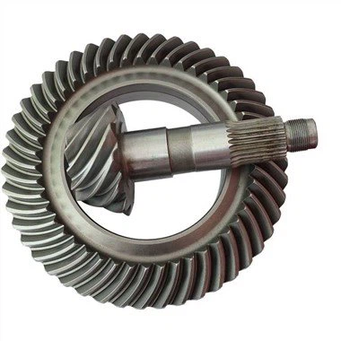
 Beval GearBevel gears are gears where the axes of the two shafts intersect and the tooth-bearing faces of theAdd to Inquiry
 -
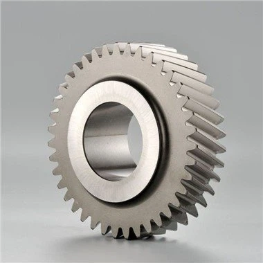
 Spiral GearSpiral gear is the abbreviation of helical cylindrical gear, that is, the cylindrical gear whoseAdd to Inquiry
 -
 Sun GearThe sun gear, together with the planetary gears, internal gears, and planetary carriers thatAdd to Inquiry
 -
 Worm GearA worm gear is a gear consisting of a shaft with a spiral thread that engages with and drives aAdd to Inquiry
 -
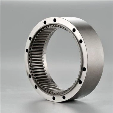 Annulus Ring GearThe annulus ring gear is a very important part of the planetary reducer, which provides a rotatingAdd to Inquiry
 -
 Electric Drive GearThe central motor drive system consists of motor, fixed speed ratio reducer and differential. InAdd to Inquiry


- Tel: +86-579-88301121
- Mob: +86-13858988130
- Email: jhjgcl@sina.com
- Add: ChengNan Industrial District, LanXi, Zhejiang, P.R.C.

High torque, small size
The most obvious way to increase torque is to use a bigger motor. However, in many cases, space for motor installation is limited, especially if the motor is installed inside machines, robots, or other equipment. Torque can also be increased by increasing the electrical power input. But if more electricity is used, the motor will generate excessive heat, leading to decreased efficiency and eventual failure.
Reduction gears can be used to generate several hundred times the torque from the same motor. This means more torque can be obtained from the same size motor, or a smaller motor can be used to maintain the current torque requirements. In addition, the appropriate amount of electric power can be used so excessive motor heat can be avoided and the motor can run safely and efficiently.
Why Are Reduction Gear Needed?
Most motors have a fixed range of rotational speed and torque that is most efficient for their operation. However, work that needs to be done generally requires much lower speeds and higher torque than what the motor can deliver efficiently.
In other words, the motor has high speed and low torque, while the work requires low speed and high torque. Attempting to complete the work with just a motor will require operation outside of the efficiency zone, leading to excessive heat generation, shorter lifespan, and other negative effects unless a larger, more costly motor is used.
In such cases, a reduction gear can be used to reduce the speed and increase the torque of the motor output. The appropriate gear ratios can be selected to achieve the required speed and torque at the output gear while the motor operates in its most efficient range.
The Types of Reduction Gears and Features of Each
Planetary reduction gear gear
Planetary reduction gear gears have a sun gear in the middle and multiple planetary gears inside a ring gear. There are fixed and movable internal gears. Using gears with different numbers of teeth allows these reducers to produce high gear ratios and large reductions in speed.
Strain wave reduction gear gear
Strain wave reduction gear gears are high-performance reduction gears that use the strain wave gearing principle. They are driven by an elliptical wave generator that is placed inside a thin, cup-shaped elastic metal body. When the wave generator rotates and creates waves in the elastic metal body, the body comes into contact with the external circular gear. As the teeth of the elastic metal body engage the teeth of the external circular gear, the body rotates.
In addition to high torque, low inertia, and compact size, strain wave reduction gear gears have almost no backlash, and have low vibration and noise, allowing for quiet and stable operation.
Parallel shaft reduction gears
Parallel shaft reduction gears combine several stages of spur gears (which have excellent power transmission) and helical gears (which operate quietly) to reduce rotational speed. One notable feature is that the input and output shafts are parallel to each other.
A wide range of reduction gear ratios can be set by combining gears in several stages, making this type of reducer useful in a variety of applications.
Worm reduction gear gear
Worm reduction gear gears combine a worm gear, which is a threaded gear, with a worm wheel, which is a helical gear. The worm gear acts as the input axis and the worm wheel acts as the output.
Move separately. The input gear rotates perpendicular to the output gear and allow worm gears to achieve high reduction ratios in a single stage.
Energy is transmitted from the worm gear to the worm wheel through a sliding motion, which can tend to generate heat, and the duty factor is generally set very low. On the other hand, worm gears tend to be much quieter than planetary gears.
Bevel reduction gear gear
Bevel reduction gear gears use a type of bevel gear known as a hypoid gear to reduce the input speed. The axis of the output is rotated 90 degrees in relation to the input.
Bevel gears have strong teeth, so they perform well even under heavy loads and exhibit high durability. In addition, they feature high duty factors and are less likely to retain heat than worm reduction gears.
Gear reducers, or reduction gears, are necessary for high efficiency machinery operating at elevated speeds. For the speed produced by the machinery to be practical, it has to be reduced to a lower speed to meet the needs of the powered application. The basic construction of a gear reducer consists of a large gear that is positioned with a smaller gear with both gears turning together.
In the case of a single gear reducer where a large gear is connected to a single smaller gear, the smaller gear makes two turns for every one turn of the larger gear. With the multiple turns of the smaller gear, there is greater speed but a loss of torque.
The reduction gear process takes place at preset ratios that meet the characteristics of the input and output gears. A gear reducer achieves the change in energy by changing the ratio of the moving gears.

Gear ratio
The gear ratio is a way of measuring how different sizes of gears interact to transfer energy. The essential aspect of this calculation is the measurement of a circle, which is a major part of gears. The determination of the gear ratio can be understood by examining the circumference of a circle. A gear that makes two rotations to turn a larger gear once has a ratio of 2:1, which means that the output speed has been cut in half.
This example simplifies more complex gear reducers with several gear pairs in a series for converting revolutions per minute (RPMs) to torque. The example below presents a slightly more complex gear reducer with an idler gear between the small gear and the larger.
In determining the gear ratio, the only gears that influence the gear ratio are the drive gear and driven gear. Any gears inserted in between the two are not calculated in the gear ratio. An easy way to calculate the gear ratio is to count the number of teeth in the drive and driven gear. In the example, the drive gear has seven teeth while the driven gear has 30. The drive gear has to turn 4.3 times before the driven gear will turn.
Reduction gear torque
Torque is a rotational force that is received by the gear reducer and changed into a different force and speed with the amount of power remaining the same. Gear reducers are a gear or series of gears designed to reduce the torque of a motor, which increases in direct proportion to the reduction of rotations per unit of time or revolutions per minute. This is accomplished by base mounted or shaft mounted gear reducers.
Gears are used to multiply or divide torque, which is determined by the size of the gears. The ratio of the gear sizes increases or decreases torque, which is the foundational aspect of the operation of a gear box.
Drive gear
Drive gears or gear drives are designed to change the speed, torque, or direction of a rotating shaft. In their simplest form they are a small gear that drives a larger gear connected to the output shaft. They are essential for providing variable output speed from a constant power source.
In the image below, the silver worm shaft with a worm gear is the drive gear for this two gear gear reducer. The driven gear is the brass colored worm wheel of the worm gear set.
Driven gear
The driven gear is connected to the output shaft and transfers the reduced power to the application. They are the larger of the gear set regardless of how many gears there are in the series and come in a variety of shapes. In the compound gear train example below, there are two driven gears connected to different shafts, B and C. The gear ratio for the driver gear for shaft B and the one for shaft C is the same.
Reduction Gear Types
Bevel gear reducers have an angular bell crank that allows users to change the rotation of the system from transverse to longitudinal. They are compact and can handle a great deal of power from three phase asynchronous motors, synchronous motors, or asynchronous servo motors.
As with helical and hypoid gear reducers, bevel gear reducers operate quietly at a very high performance level with exceptional energy efficiency.
With a cycloidal gear reducer, the input shaft drives a bearing assembly that drives a cycloidal disc that is connected to an output shaft. The cycloidal has teeth that engage with a cam follower that has pin or needle bearings. The cam rotation produces a rotation of an output shaft at a much lower speed and higher torque than the input shaft.
The major benefit of cycloidal gear reducers is the elimination of backlash, which leads to higher precision and accuracy that is needed in robotic applications and machine tools. Additionally, cycloidal gear reducers have rolling contact that leads to less wear.
A gear train gear reducer includes a series of gears that transfer power from an input shaft to an output shaft. They are used for applications that require a great deal of power and operate on parallel axes. There are several versions of gear train gear reducers with two gear trains being the simplest with a drive gear and driven gear. In multiple versions of gear trains, there is a drive gear with driven gear with idler gears in between.
Helical gear reducers are another form of space saving gear reducer with durability and high overload capacity. They are used for forward speeds where the gear train is operating at medium to high speeds. The tooth traces of helical gears are slanted creating a higher meshing ratio to produce less noise and make them stronger. Their synchromesh design never disengages and provides more surface area.
The angular cut of the helical cut of helical gears allows for the teeth to be longer but have the same number of teeth as a spur gear.
Hypoid gears are cone shaped that send power between non-intersecting shafts. The small hypoid pinion side is offset from the hypoid gear side, which makes them able to pass without interference. The large contact ratio of hypoid gears allows for heavier load transmission with smooth meshing. As with helical gear reducers, the smooth meshing of hypoid gears produces less noise. Hypoid gear reducers are capable of very high speed reduction.
It is common to find hypoid gears being used when the angle is square and the distance between axes is small. Hypoid gears are used as an intermediate between bevel and worm gears.
Magnetic gear reducers are a very unique form of gear reducer that uses magnetic attraction instead of physical contact. They do not have gear teeth but use opposing magnets that repel each other, which makes them capable of applying pressure regardless of the angle. Magnetic gears create motion just like traditional gears without touching, making them unaffected by wear.
Additionally, magnetic gears do not require lubrication or sealed barriers. They are manufactured using permanent magnets or electromagnets.
A planetary gear reducer has a sun gear, planet gears, and large ring gear. The planet gears depend on the support of the output shaft, inner gear ring, and the sun gear. The power drives the sun gear in the middle of the gear configuration, which drives the planetary gears to rotate following the inner gear ring. The rotation of the planet gears drives the output shaft connected to the output power.
A planetary reducer has a long service life, small size, high carrying capacity, low noise, high output torque, and high efficiency. It has power splitting and multiple tooth meshing to produce a reducer with wide versatility.
Spur gear reducers have straight teeth that are parallel to the axis. They are the most common and frequently used type of gear reducer and can include multiple gears with multiple gear ratios. Spur gear gearboxes have exceptionally high efficiency with very low backlash and are very rugged and stable.
A worm gear reducer has a worm pinion input and an output worm gear with a right angle orientation. They are used to take a motor’s speed and produce a lower speed output with a higher torque. Worm gear reducers are ideal for saving space due to their sleek design and the small diameter of their output gear as well as the excellent speed reduction using a small package.
How to Choose a Reduction Gear


There are certain factors that have to be evaluated before deciding to purchase a gear reducer. The main purpose of a gear reducer is to adapt the characteristics of torque and speed of the input and output axis of a mechanism. It is for this reason that it is necessary to understand the torque and rotational speed of the application.
Torque of a motor
A gear reducer increases the torque of a motor and creates a new torque for the receiving application. As an assist to customers, manufacturers express maximum and minimum torque in newton meters (Nm) for their products with the torque density varying between different gear reducers.
Speed of a motor
The second purpose of a gear reducer is to reduce motor speed, which is expressed in terms of the reduction ratio. The rotational speed of a motor is changed by the rotational ratio to produce the output rotational speed, which is described in revolutions per minute.
Reduction gear selection
At this stage of the selection process, an expert, engineer, or designer that is knowledgeable in gear reducers is necessary since there are so many types of gear reducers designed to meet the requirements of a wide assortment of functions and parameters. The configuration of the input and output shafts are the first criteria related to choosing the type of gear reducer.
Reduction gear dimensions
To decide on the dimensions of a gear reducer, it is important to choose the right shaft, which can be orthogonal, coaxial, and parallel. Each of these shaft types have a different orientation in regard to the gear reducer, which are perpendicular, aligned and parallel.
Motor performance
In some applications, motors experience shock or cyclic loads. When choosing a gear reducer, it is important to factor in these conditions in order to allow the gear reducer to be able to deal with the increased torque.
Operational efficiency
Choosing a gear reducer that operates efficiently is necessary regarding its cost. The correct one for an application can be beneficial in regard to long term costs.
Choosing a gearbox
Planetary reduction gear
Planetary gear reducers are used with applications that demand fast acceleration, low speed, and high torque. They are used in machine centers, machine tools, and agricultural operations.
Worm gear
Worm gear gear reducers are used in applications with a high transmission ratio. They are less costly than other gear reducers and operate very quietly. Worm gear gear reducers are used on conveyors, winches, and material handling due to their non-reversibility.
Choosinggear train
Gear train gear reducers are designed for high powered applications and save money on maintenance due to their exceptional performance and low reduction ratio.
Bevel reduction gear
Bevel gear reducers permit operators to change their rotation scheme. They are small, strong, and can endure a great deal of force. The drawbacks to bevel gear reducers is their poor performance, high cost, and constant need for maintenance. Bevel gear reducers are found in farm equipment and heavy duty conveyors.
Choosing the right reduction gear
Gear reducers are critical factors in a wide assortment of machines and are important components for the smooth operation of the machines. The correct selection of a gear reducer ensures the effectiveness and efficiency of a mechanism. A qualified manufacturer with the proper knowledge and tools can guide the perfect solution for any application.
Reduction Gear Maintenance
Lubrication material
Every gear reducer manufacturer sells or recommends the correct lubrication material for their products. The lubricant has to have the right properties to enhance performance. Initially, during the break in period, it may be necessary to filter the lubricant to remove contaminants. The quality of the lubricant should be checked regularly as well as its level.
Reducer contamination
The only thing that is permitted in a gear reducer is the lubricant. Dust and water that can enter through faulty seals can cause extensive damage to the gears.
Storage for reduction gear
Gear reducers are stored in clean, dry, and climate controlled conditions with all of its covers, vents, and drains closed and sealed. Though the gear reducer is not in operation, its lubrication cycle must be maintained. During the process, it should be rotated to ensure the even distribution of the lubricant.
Reducer vibration or noise
The initial indications of problems with a gear reducer are noise. Assessment can be made by operating it without a load. Essentially, noise and vibration are an indication of the need for gear reducer overhaul or replacement.
Reduction gear overheating
Overheating is an indication that the gear reducer is not receiving sufficient lubrication. The harm of overheating can be prevented by regular checks of the surface temperature of the gear reducer. Overheating can be due to friction between the gears caused by a lack of lubricant.
Our Factory
Founded in 1992, JinHua JingGong automotive gear Ltd., Co. was originally established in JinHua, ZheJiang. Major products are transmission gear and gear shaft parts. As a 30-year-old mechanic manufacturing company, the persistency on automotive industry has always driven us to be creative and keep forging ahead. Currently, we have capability to produce 500,000 parts per year and independently develop new transmission gear boxes, and more importantly, we can turn a blueprint into a fact. Holding the IATF 16949 certificate, JingGong is currently a supplier of DFAC. Our products cover full-range of transmission field, including trucks, construction machinery, farm machinery and mining machinery. Also, we have developed transmission parts of first batch EV trucks in China.

Certificate

FAQ
We're professional reduction gear manufacturers and suppliers in China, specialized in providing high quality customized service. We warmly welcome you to buy high-grade reduction gear at competitive price from our factory.
induction gear, gas motor gear, Reduction Gear